
GhostLink P1
Owner's guide for the GhostLink P1 handheld: battery safety, charging, ports, wiring, pinouts, flashing and maintenance
On this page
The GhostLink P1 is GhostESP’s own open-source handheld: an ESP32-1732S019 “CYD” board (1.9" display, ESP32-S3) as the main unit, an optional ESP32-C3 SuperMini as a second GhostLink radio, an IP5306 charge/boost board, a microSD slot, a 5-way nav pad and a user-replaceable 18650 cell, all in a 3D-printed shell you can reprint or reskin.
Open files, parts list and build instructions live on ghostesp.net/hardware. Pre-assembled units are sold on shop.ghostesp.net, with the 18650 cell not included (lithium shipping rules).
At a glance
| Action | How |
|---|---|
| Power on | Tap the button on the back of the shell |
| Power off | Hold the same button down |
| Battery level | 4 red LEDs on the back: 25 / 50 / 75 / 100% |
| Charge the battery | Plug into the top USB-C jack; this is the only charging port |
| Flash main firmware (core) | CYD USB-C port on the left edge |
| Flash aux radio firmware (peer) | Top USB-C jack |
| Install the 18650 | Positive (+) end to the dome contact, negative (-) to the spring |
| Battery polarity | Danger: never install the cell backwards. Reverse polarity has no protection on the IP5306 charge board or the aux radio; a backwards cell can burn both out, and a hard short is a fire hazard. |
Ports
| Port | Location | Does |
|---|---|---|
| Aux radio USB-C | Top edge, recessed panel-mount jack | Charges the battery; flashes the peer firmware |
| CYD USB-C | Left edge, on the display board | Flashes the core firmware, serial console, USB power; does not charge the battery |
A cable in the left (CYD) port keeps the device running but never puts charge into the cell.
Battery & charging
The P1 runs on a single user-replaceable 18650 cell in a spring-loaded cradle at the bottom of the shell.
Danger: Never install the cell backwards. Reverse polarity has no protection on the IP5306 charge board or the aux radio; a backwards cell can burn both out, and a hard short is a fire hazard.
- Orientation: the positive (+) terminal goes to the dome contact, the negative (-) flat end to the spring contact.
- Identifying the ends: the negative end is completely flat; the positive end is a small raised terminal, sometimes with a visible pip or button (button-top cells). Both ends are round and the cell will sit either way, so trust the + / - markings on the wrapper, not shape alone.
- Cell quality: use a quality, undamaged cell (Samsung, LG, Molicel, Sony, …). A flat-top cell fits the cradle best; longer protected cells may not fit. Never use cells that are dented, rusted, punctured or swollen.
Charging
Important: Only the top USB-C jack charges the battery. The CYD's left-edge USB port is data-only.
- Charger: any standard 5V USB source of 1A or more; a phone charger works.
- Cable: USB-A to USB-C cables are the most reliable. Some USB-C to USB-C cables (laptop chargers, power banks) won’t work because the device doesn’t negotiate power; if nothing happens, try a USB-A to USB-C cable.
- While charging: the device can be used normally. With the typical ~1A charge current, a 2500-3000 mAh cell takes roughly 3 hours from flat.
- Don’t overdo it: don’t leave the cell charging unattended for days, and stop using it if it gets hot or swollen.
Flashing firmware
The P1 is a two-radio GhostLink setup; each radio runs its own build:
| Radio | Board | Release build |
|---|---|---|
| Main (display, core) | ESP32-1732S019 (S3) | GhostLink_P1_Core.zip |
| Aux radio (peer) | ESP32-C3 SuperMini | GhostLink_P1_Peer.zip |
- Core build flashes through the CYD USB-C port (left edge).
- Peer build flashes through the top USB-C jack (the aux radio’s own port).
- Both flash with the same tools as any other board; see the Installation Guide and Firmware Updates.
- After both radios are flashed, they talk to each other over GhostLink; see Dual Communication (GhostLink) for pairing.
SD card
The microSD module sits on the right of the mid band under a screwed retainer: insert the card pins-first until it clicks. GhostESP uses it for storage, scripts, asset packs and data logging; see SD card and Storage Layout.
Wiring & pinouts
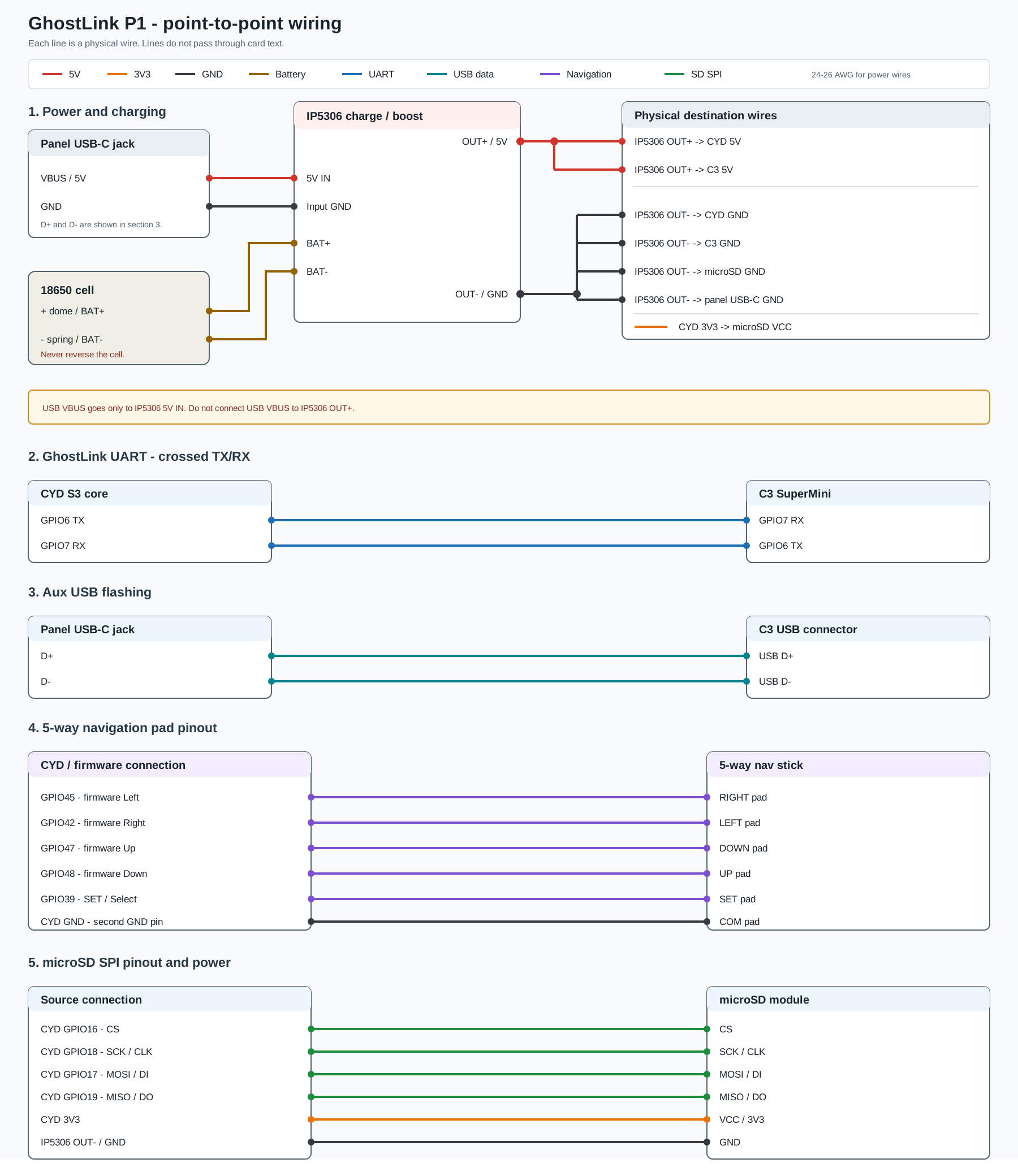
Every module in the shell wires straight to the ESP32-1732S019 (S3) board’s GPIO rows - there’s no glue logic in between, so the tables below are the full wiring map for the user-serviceable parts. Pin numbers come from the P1 Core firmware config (configs/sdkconfig.ghostlink_p1_core).
5-way nav pad
The nav pad is a simple button matrix: pressing a direction shorts that pad to COM. The direction pins are active-low with internal pull-ups, and COM connects directly to the second GND pin on the CYD. Wire by firmware function, not by the pad’s label - the pad silkscreen is crossed against the firmware (see the note below).
| ESP32-S3 GPIO (firmware function) | Connect to joystick pad |
|---|---|
| GPIO45 (firmware Left) | RIGHT pad |
| GPIO42 (firmware Right) | LEFT pad |
| GPIO47 (firmware Up) | DOWN pad |
| GPIO48 (firmware Down) | UP pad |
| GPIO39 (firmware Set / Select) | SET pad |
| CYD GND (second GND pin) | COM pad |
Crossed by design - don’t match labels: the joystick’s pad labels are hooked up reversed against the firmware’s function names, so that pressing the physical left button lands on the firmware’s Left pin: the pad printed LEFT goes to GPIO42 (firmware Right), RIGHT goes to GPIO45 (firmware Left), UP goes to GPIO48 (firmware Down) and DOWN goes to GPIO47 (firmware Up). The firmware’s own pin assignments (
L_BTN=45,R_BTN=42,U_BTN=47,D_BTN=48) stay exactly as configured - only the physical wiring crosses them. Reading the GPIO column for the direction you want and hooking up the opposite pad label is the correct build.
microSD slot (SPI mode)
The P1 uses the microSD board in SPI mode (CONFIG_USING_SPI, not SDMMC). The module’s standard 6-pin header maps like this:
| SD module pin | ESP32-S3 GPIO | Notes |
|---|---|---|
| CS | GPIO16 | chip select |
| CLK / SCK | GPIO18 | SPI clock |
| MOSI / DI | GPIO17 | SPI data out (board → card) |
| MISO / DO | GPIO19 | SPI data in (card → board) |
| VCC | 3.3V | power to the module |
| GND | IP5306 OUT- / GND | direct ground wire from the IP5306 |
The SD bus shares the display board’s SPI bus, so these pins are fixed on the P1 - don’t reuse GPIO 16-19 for anything else. If you build your own board variant, the pins can be changed at runtime with sd_pins_spi <cs> <clk> <miso> <mosi> (see SD card).
GhostLink aux radio (optional)
The aux radio (ESP32-C3 SuperMini by default) talks to the core over the GhostLink UART. On the P1 the firmware remaps both ends to a straight-through pinout - core TX on GPIO5 and RX on GPIO6, peer TX on GPIO6 and RX on GPIO5 - at 115200 baud:
| Core (S3) | Aux radio (C3) |
|---|---|
| GPIO5 (TX) | GPIO6 (RX) |
| GPIO6 (RX) | GPIO5 (TX) |
| IP5306 OUT- / GND | C3 GND |
The wiring is straight-through (core TX5 to peer RX5, peer TX6 to core RX6), not crossed like the generic GhostLink defaults. These are the P1 firmware defaults and can be changed at runtime with commsetpins <TX> <RX>; see Dual Communication (GhostLink).
Maintenance & upgrades
Nothing is glued or locked down, so any module can be swapped:
- Aux radio: held by a 3-screw retainer. Replace it in minutes, or swap in an S3-Zero / ESP32-C5 module if it fits the socket (pinout permitting).
- microSD board / IP5306: each held by its own 2-screw retainer.
- Shell: front and back halves close with 4 × M2 screws into heat-set inserts; reprint it whenever you like (STLs are CC BY-NC-SA licensed).
- Display: the 1.9" glass is exposed on the front; don’t press hard on it, the 5-way nav handles the buttons.
Faulty module? Replace just that part; every component is off-the-shelf and the parts list on the hardware page has the exact links.
Troubleshooting
- Left port plugged in, battery never charges: expected; only the top port charges. Swap cables.
- Nothing happens when a USB-C to USB-C cable is plugged in: try a USB-A to USB-C cable; many USB-C to USB-C cables won’t power or charge these boards.
- Device won’t power on: tap the back button, then confirm the cell is seated the right way round.
- Battery won’t charge: check the cell orientation (positive against the dome contact) and that the charger is in the top USB-C jack.
- No display, but the device runs: re-check the CYD board’s four M2 screws and its connector seating.
- GhostLink shows no peer: flash both radios (
GhostLink_P1_Core+GhostLink_P1_Peer) and re-pair per the GhostLink guide.
Related tasks
- Hardware page on ghostesp.net: STL downloads, parts list and shop
- Installation Guide
- Dual Communication (GhostLink)
- SD card storage